Quantity : 1
Hign-concerned Chemical : None
Package : SMD
Model Number : NE555
Dissipation Power : ...
Supply Voltage : ...
Application : All
Type : Module
Operating Temperature : ...
Origin : China
Condition : New
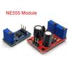
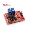
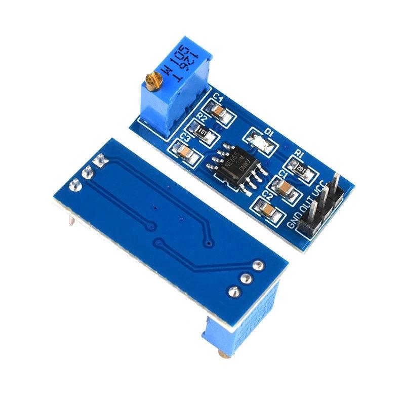
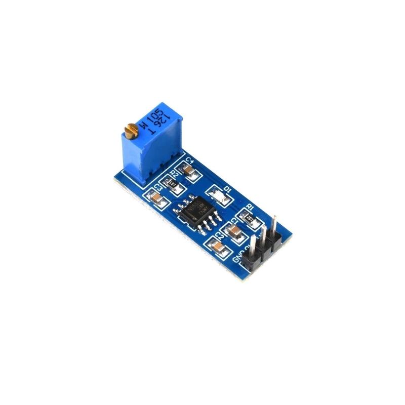
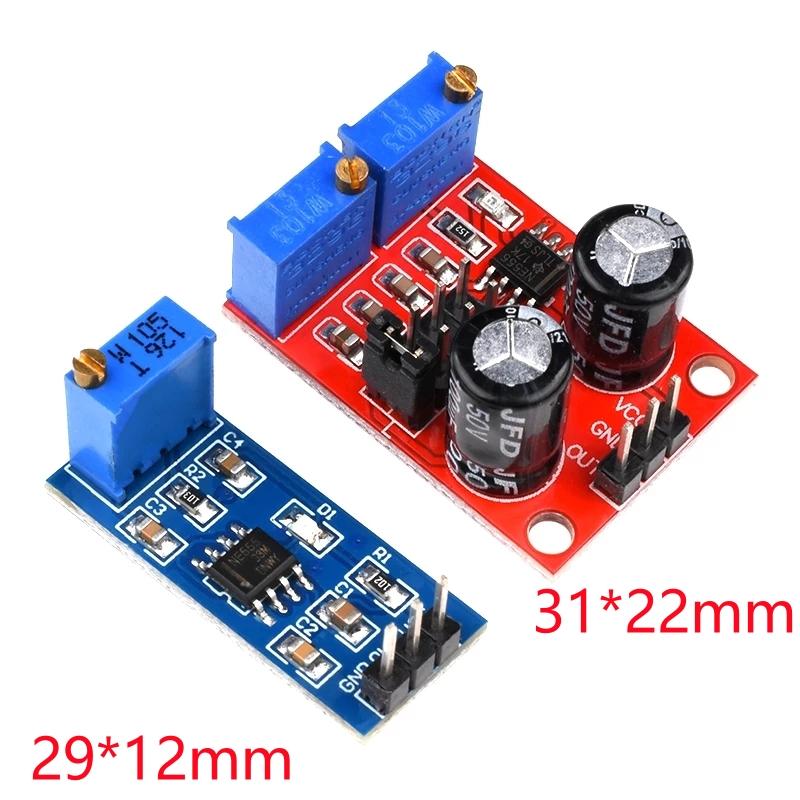
NE555-Blue:
1. Onboard NE555 IC.
2. Single channel signal output, the output duty cycle about 50% square wave.
3. Plate load resistor, adjust the resistance to control the output frequency.
4. Onboard power indicator.
5. Working voltage: 5V~12V.
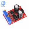
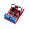
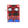
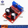
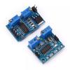
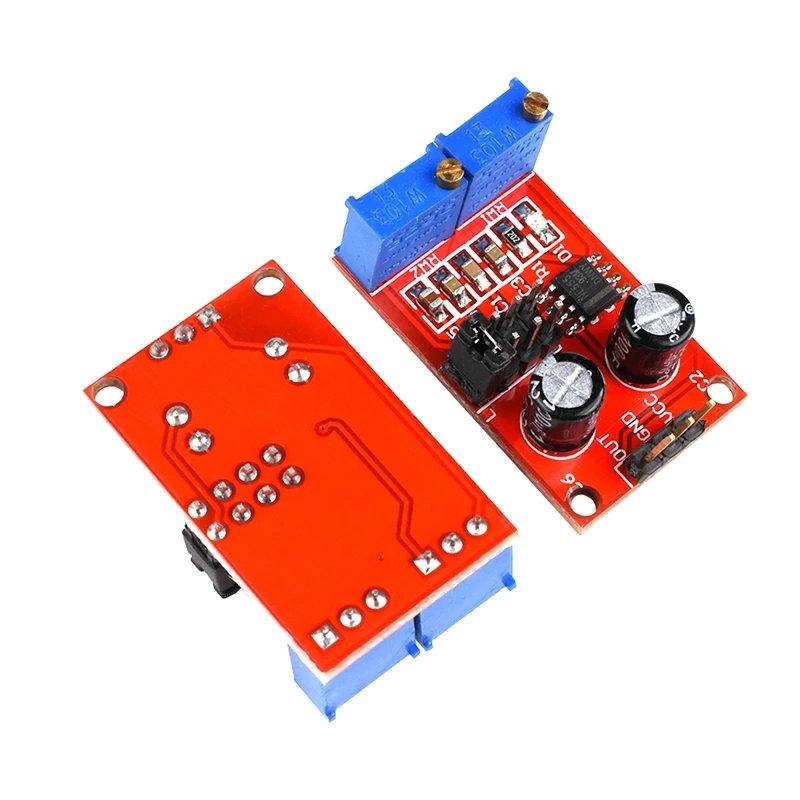
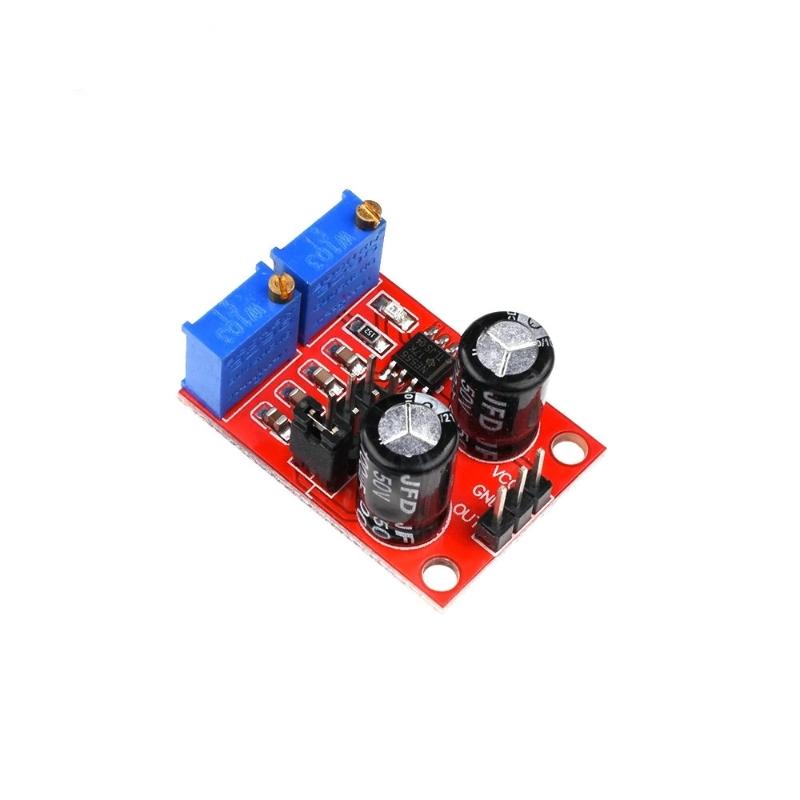
NE555-Red:
1, Size: 3.1CM * 2.2CM
1, the main chip: NE555;
2, Input voltage: 5V-15VDC. 5V power supply, the output current can 15MA around; 12V power supply, the output current can 35MA around;
3, the input current: 100MA
4, the output amplitude: 4.2V V-PP to 11.4V V-PP. (Different depending on the input voltage, the output amplitude will be different)
5, the maximum output current: 15MA (5V power supply, V-PP greater than 50%), 35MA (12V power supply, V-PP greater than 50%)
The scope of this module:
1 is used as a square wave signal generator generates a square wave signal used for experimental development.
2 to drive a stepper motor for generating a square wave drive signal.
3 adjustable pulse generated for use by MCU.
4 adjustable pulse generation, control circuitry associated.
Advantages:
1, the output with LED indication, there is no output straightforward (low LED volume, high LED off frequency is relatively low, the LED flashes);
2, the output level selectable frequency range, the output frequency is more continuously adjustable;
LF file: 1Hz ~ 50Hz
IF file: 50Hz ~ 1kHz
High-frequency file: 1KHz ~ 10kHz
HF file: 10kHz ~ 200kHz
3, the output duty cycle can fine-tune, duty cycle and frequency is not separately adjustable, adjusting the duty cycle will change the frequency
4, the output frequency is adjustable;
Period T = 0.7 (RA +2 RB) C
RA, RB is 0-10K adjustable;
Low profile when C = 0.001UF;
IF stalls C = 0.1UF;
High-frequency file C = 1UF;
HF stalls C = 100UF, so the frequency of the waveform buyers can own calculations
The line layout is compact and regular, with good electrical insulation and mechanical stability, and can maintain stable performance under different temperature and humidity environments to ensure accuracy and reliability.
In circuit design, carefully planned lines are like precision transportation networks, and lines of different widths and spacings undertake different currents and signals transmission tasks respectively. The key signal lines are impedance matching processing, which greatly reduces signal reflection and attenuation and ensures the stable transmission of high-frequency signals.
All kinds of electronic components are soldered on the circuit board, and the solder joints are full, round, and firm and reliable. Core components like chips are perfectly connected to the circuit board through fine packaging processes to achieve high-speed data processing and interaction.
This circuit board has a wide range of responses in many fields. Whether in the industrial control field that requires extremely high stability or consumer electronics field that pursues extreme performance, it can provide solid guarantees for the stable operation of the equipment with its excellent design and reliable performance, and help various electronic devices play a powerful role.


 Reembolso por não entrega